I'm in the process of constructing/setting up my office in the house, and for lighting, I have decided that I want to use xmas light-style lighting. Many years ago, I used to light my room with multicolored incandescent lights. I loved the warm indirect glow, and smooth light without a single light source. This time, I'm going to take it a step further.
While there's nothing about this project yet that is really innovative over what others have done, it is the first step to getting the office lighting done. The real fun will come into play once I'm able to hang this up, and start programming effects, and tying those effects in to physical or time-based events.
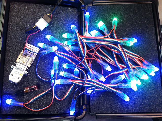
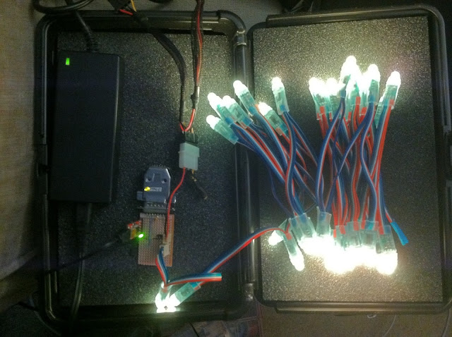
A couple years back I picked up a strand of addressable LED lights, similar to this one, available at adafruit.com. I got a strand of 50 lights, blew out one of them while being stupid, and used a few of them in Jasper's Toy Box (posts to come about that eventually), so I'm left with 42 lights. A nice number.
In any event, the plan is to hang them up around the upper perimeter of the room, and it will give a nice comfortable glow to illuminate the room. I can also extend it by doing lighting effects with the color. For example, in the evening I can have all of them dim blue, and randomly twinkle one to white, to simulate a star in the sky. I could also tie them in to an automation system to glow a particular corner of the room red or yellow when i have email from a specific person. I could also adjust their color based on the content of my monitor, or the light outisde, etc.
The basic design for the control circuitry is that there will be an Arduino-based AVR micro (actually one of the D-15 servo controllers I've appropriated), which is perfect, since the strands only need two lines to control them. The host computer will send down codes to address the LEDs (set all to color X, set led Y to color X, etc) and this will pass on the content to the strand, and twiddle the data lines and all of that fun stuff. I had considered putting more "smarts" into the micro, but the amount of space in there would severely limit the kind of content I could "display", so I decided to put all of the grunt work back on the host computer.
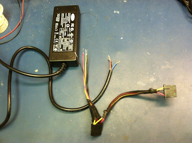
To power it, I needed to get a 5 volt power supply. I snagged a power brick from an old external drive case, as well as a standard PC power connector, from a failed power supply, and spliced the two of them together.
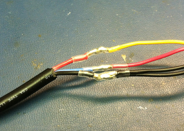
Copious, yet appropriate amounts of heat shrink tubing and splicing some wires yielded a nice power supply.
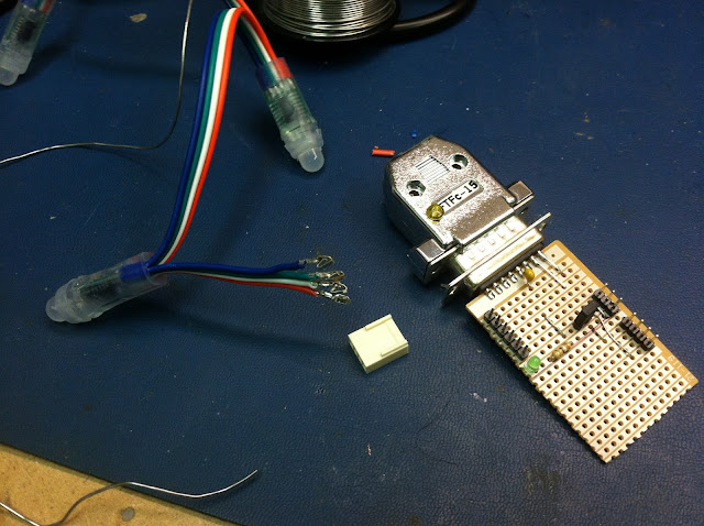
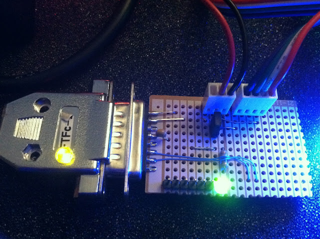
Next, I built an interface board to tie it all together. The ports on the board are (left to right) - 6 pin FTDI interface for serial IO, 2 pin jumper (power the D15 from the power supply rather than FTDI source), 3 pin power, 4 pin light strand connector. You can also see in this picture, the process of crimping the terminals for the molex connector on the LED strand's wires.
I kept the layout and pinout of the FTDI the same as I used for my serial node experiment. This will help me plug that connector in correctly. I still need to add visual cues (colored sharpie markings) to help me align the pins correctly. The power connector has GND on pins 1 and 3, and +5V on pin 2. Keeping it symmetrical will help me always plug it in correctly, reducing the chance that I will blow it all up. The 4 pin connector is the same pinout as the wiring of the LEDs. GND, Data, Clock, +5.
The jumper on the board (dis)connects the power header from the D15 and FTDI portion. If I make standalone firmware for it, I can power everything from the power supply, if need be. The tiny green LED on the board just lights when the D15 has power. A nice indicator in case everything else is not functioning.
The protocol I used for this is very simple. There's a command character sent through serial, then the data for that command. If the firmware is expecting a command character but gets something it doesn't understand, it just keeps checking the serial input for a command it knows. The protocol is as follows:
p<index of LED><red value><green value><blue value>
Five bytes. It sets the specified LED (0..42 in this case) with the specified RGB value (0..255 each). Note that this is not an ascii string, it is data. So no matter what, it is 5 bytes to change a single pixel.
f<red value><green value><blue value>
Force all of the lights to the specified color. This is handy for clearing everything to black, or flashing/fading effects.
Here's the Arduino firmware used to handle all of this: (Note: it requires that the strand's library be installed.)
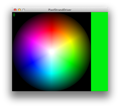
For now, that's it. I madea simple interface on the desktop side in Processing, adapted from my previous controllable pixel software, to let me click and change the color of an LED. I also added some key commands to do simple effects with the lights. (all red/green/blue. flash, etc)
Eventually, I will write better desktop software which will use the LEDs for indication of events, as well as f.lux style color effects throughout the day, audio/visual synchronization to media being played, and other effects as well as time goes on
NOTE: All of the source/projects for this are available on github.
