I'm about to start making the skeleton for my animatronic Tiki-Room Macaw. Rather than futzing with drawing up detailed plans in some cad program, Iv'e decided to instead get the basic shape made, and then just build one out of foam core. My thought was that once I have the shape worked out, I'll disassemble it and come up with plans for 3d printable parts that can be attached together, and eventually some vacuum formed parts as well for the head and beak, which need to be lightweight... although I'm starting to think that they could all be 3D printed, with a skin stretched over them for feathers and fur, after seeing the posts on Hack-A-Day about using acetone vapor to smooth out parts... anyway..
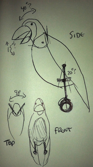
One of the things I was unsure of was the control linkages, and how the articulation points can be made. It needs to have a few points of articulation to match the birds in the Enchanted Tiki Room:
- Perch rotation - 270 degrees, spins the bird around (not shown)
- Lean - +20, -20 degrees, to lean forward and backward at the point where the legs connect
- Head yaw - +45, -45 degrees back and forth
- Head tilt - +15, -15 degrees up and down
- Beak - 30 degrees, could be all open or all closed (shown in the diagram as 15 degrees)
I was thinking that after I constructed the foam version, I could figure things out from there, but after seeing this post on Hack-A-Day with a "HOG Drive", I realized I could leverage off of this design for the head linkages.
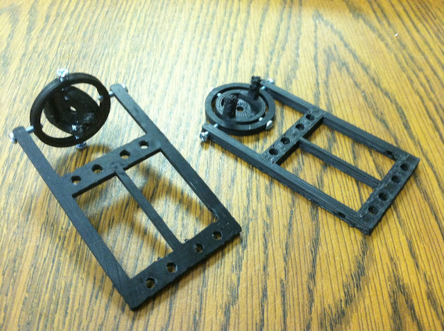
I chatted with Skip at Interlock, and by the end of this last Tuesday evening, I had two 3-D printed versions of this, using ABS, rather than the PLA material I am more familiar with. (Here's the Thingiverse link for the design.) Since I wasn't going to be mounting a motor, we (and by "we" I mean "he") replaced the motor space with a flat plate with a mounting screw hole. He also replaced the back control arm with just a peg, since the bridge-like shape wouldn't hold up properly on his printer.
The first print (on the left) has a failed control peg on the center disk. It was adding material onto printed material that didn't cool yet, so it just kinda globbed up. This was improved by Skip by adding a second post, seen in the second version on the right. He also added some material around the screw holes in the frame, to improve durability.
After printing and having this in my hand, I'm realizing that it won't quite work for me, although it does give me an excellent starting point. The center disk is too small to mount the head on. It's only about 1 1/2 inches in diameter. I think I'd want something about 2-3" in diameter, with plenty of mounting points and space for securing the head ,as well as space for wiring for the beak servo (or linear motor, or solenoid, or whatever). It really showed me the design considerations for actually constructing something, not to mention it really emphasized that whatever design I can think of, I can print... which is pretty futuristically awesome.
But the important thing is that I know have ideas to build on for the final version. I'll still be constructing a foam core model, and I'll be using this above design as a kick-off point.
(This post is cross-posted to my personal project blog as well.)

