One of our members, `Steven L Smith <http://stevenlsmith.com/>`__, has recently been bitten by the clock bug. This post is part I of a multi-part series on some of his builds.
|image0|I’ve been interested in building kits for some time now, having previously built the Theremax, various small things from Velleman, and, most recently, a morse code practice oscillator. And, I remember a place near the central Rochester, NY post office called “Rogers Pianos and Clocks” that I have fond memories of visiting and gawking at cool looking timepieces. So, when I saw the “Ice Tube” clock kit from Adafruit, I knew it would be a great next project. This ATmega-powered clock features a Russian-made IV-18 vacuum fluorescent display (VFD) tube, which, despite being blue, like modern, annoying LEDs, is actually really really cool.
 After checking to make sure I had all of the components, I
began the assembly. The first part of the build should be fairly
standard for anyone who has some electronics experience. All you have
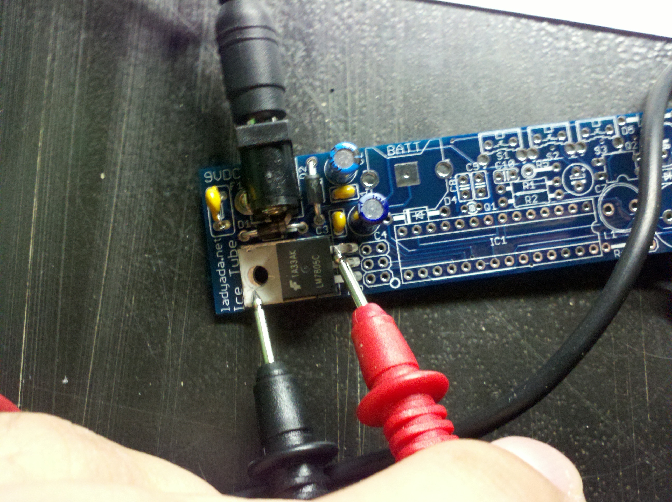
to do is assemble a simple regulated 5v power supply. Using the
provided regulator IC, and capacitors to smooth everything out, my 5v
power supply clocked in at 4.99 volts. Not too shabby.
After checking to make sure I had all of the components, I
began the assembly. The first part of the build should be fairly
standard for anyone who has some electronics experience. All you have
to do is assemble a simple regulated 5v power supply. Using the
provided regulator IC, and capacitors to smooth everything out, my 5v
power supply clocked in at 4.99 volts. Not too shabby.I continued assembly by adding a single resistor, the piezo speaker, and finally the ATmega itself (thankfully, Adafruit provided a socket for all of the ICs, which made the soldering process a lot less stressful!). At this point, plugging in the power supply resulted in a beep. All is well.
The kit, in addition to the ATmega, is driven by a 32.768 khz crystal. The crystal really does the bulk of the timekeeping by generating a steady reference frequency for the “ticks”. It was good to see Adafruit use a crystal for this clock; I think it’s going to stay accurate for a long time as a result.
Now it’s time for the fun stuff. Unlike, say, an LCD screen, or some LEDs, this clock needs around 60 volts to run its vacuum tube properly. But we’ve only got 5. So, we build a boost converter. After assembly, I used the multimeter to measure 55.7 vdc across the zener diode. The kit’s instructions say that anywhere from 40 - 70 is okay, with 60 being optimal. I’m not thrilled with that number, but it seems like it’s close enough. We’re working with high voltages here. Since I don’t feel like taking advantage of Interlock’s insurance policy, I give the capacitors time to drain, and, as the instructions suggest, do not work on the circuit until we’re below 15 volts.
Th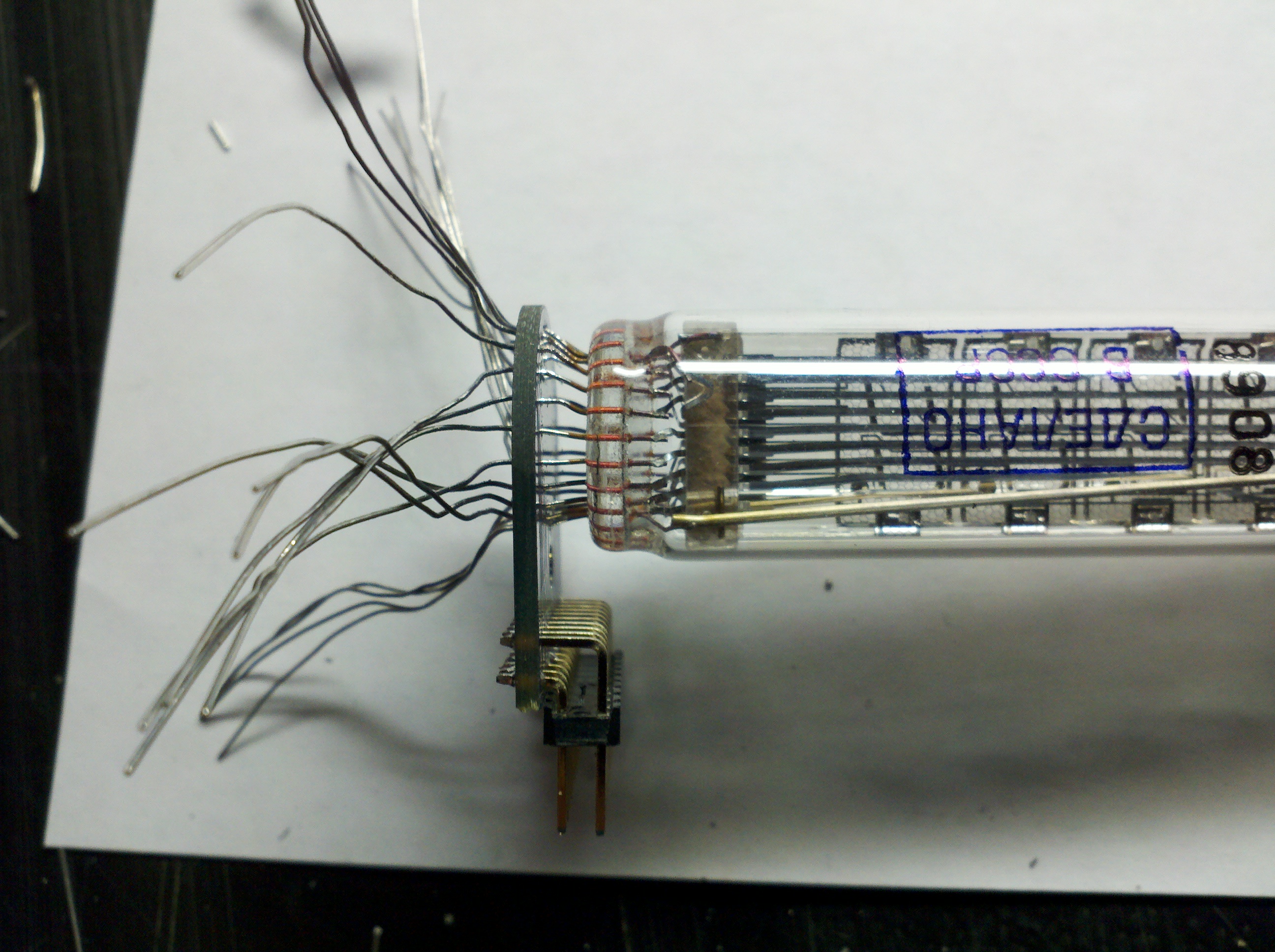 e VFD goes on a smaller PCB, and coaxing it down into
place was a frustrating experience, not unlike wiring an 8P8C ethernet
cable, except bigger, and with a lot more leads. After about 20 minutes
of carefully walking the leads through the holes, I was able to get the
tube in place. I soldered it in, plugged in the other microcontroller
(MAX6921) which actually drives the VFD segments. And... it passed the
smoke test.
e VFD goes on a smaller PCB, and coaxing it down into
place was a frustrating experience, not unlike wiring an 8P8C ethernet
cable, except bigger, and with a lot more leads. After about 20 minutes
of carefully walking the leads through the holes, I was able to get the
tube in place. I soldered it in, plugged in the other microcontroller
(MAX6921) which actually drives the VFD segments. And... it passed the
smoke test.
The remainder of the build consisted of putting in a battery backup (in case mains power is lost), adding a few control switches, and building a simple, clear case. All in all, it was a fun build, and I feel like my patience was rewarded.
In the coming weeks, I plan on building two more clocks of various types. Check back here for updates!
Additional pictures of the build:
[caption id="attachment_382" align="alignnone" width="300" caption="All
components, before starting assembly. Note that the blackened spot on
the tube is normal."]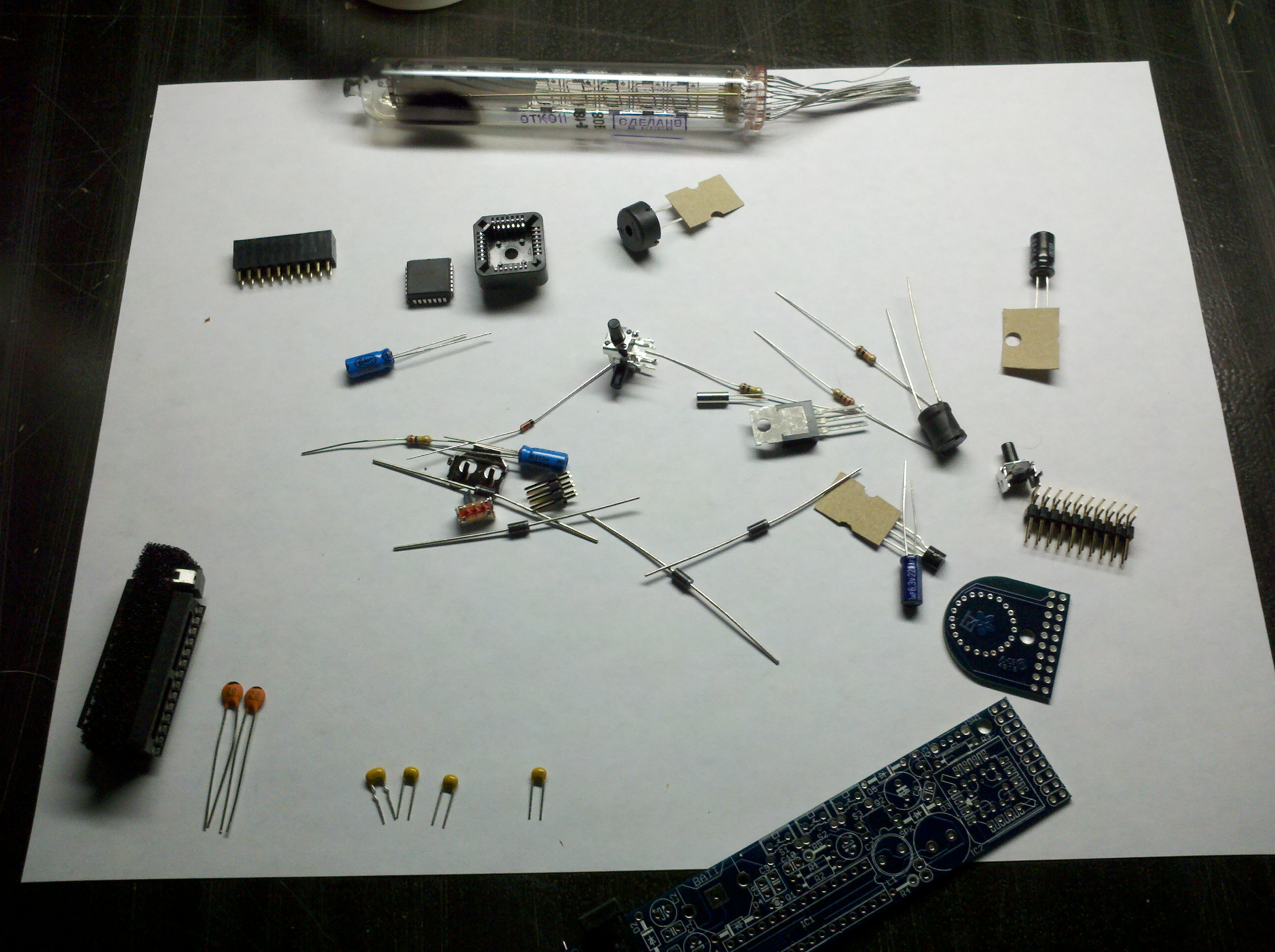 [/caption]
[caption id="attachment_386" align="alignnone" width="300" caption="VFD
Tube, as shipped."]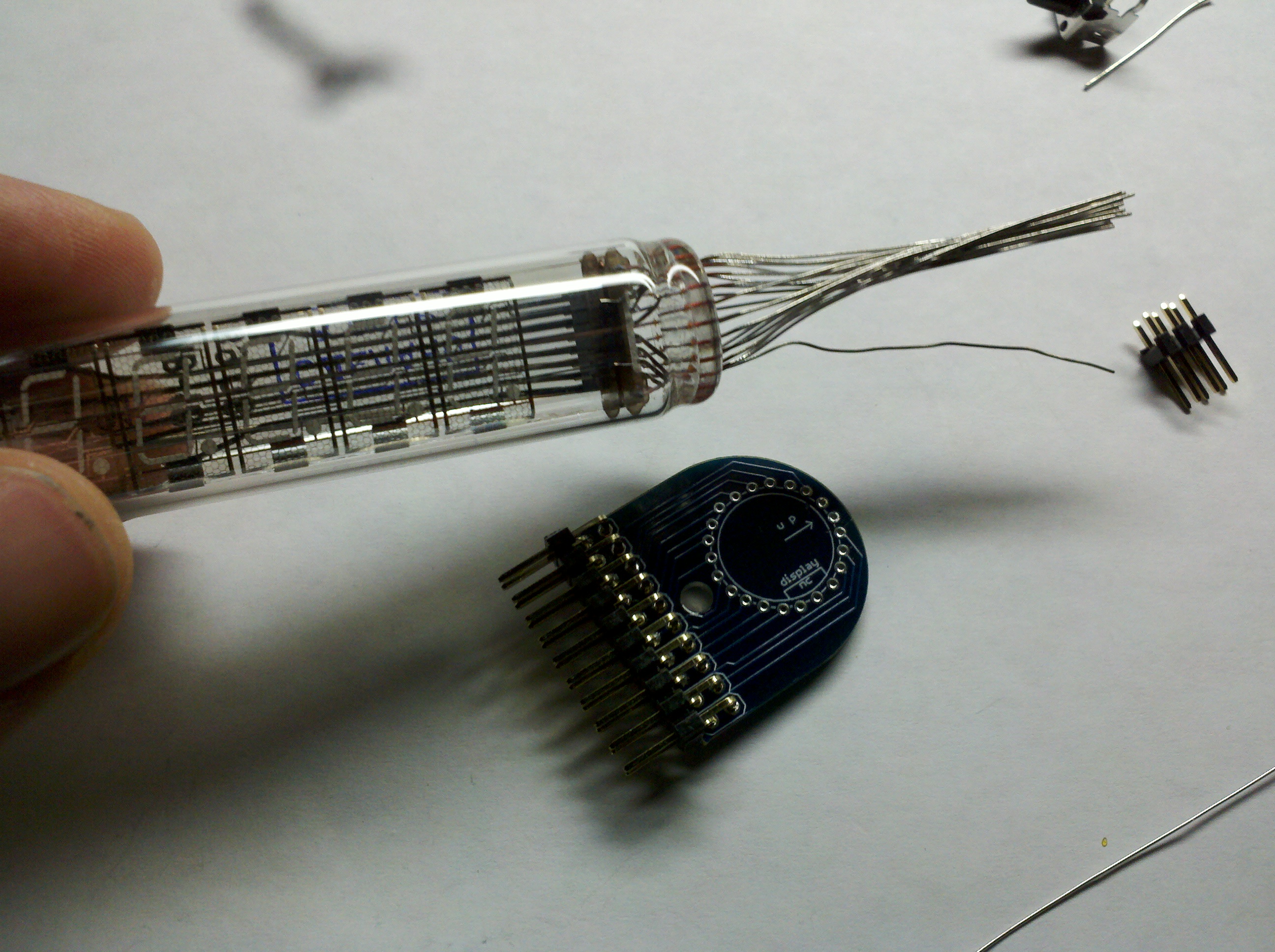 [/caption]
[caption id="attachment_379" align="alignnone" width="300"
caption="Vacuum Tube fed through PCB"][/caption]
[caption id="attachment_387" align="alignnone" width="300"
caption="Timing circuitry, including the ATmega and
crystal"]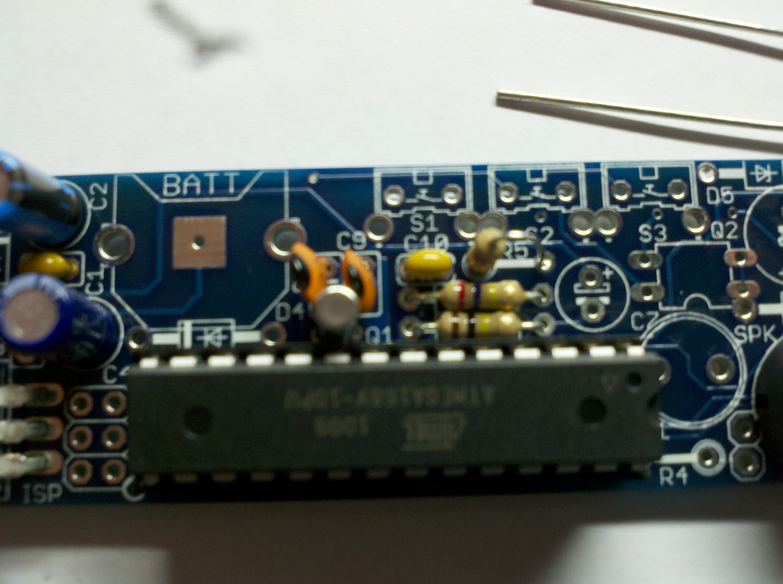 [/caption]
[caption id="attachment_381" align="alignnone" width="300"
caption="Bare Clock, without Case"]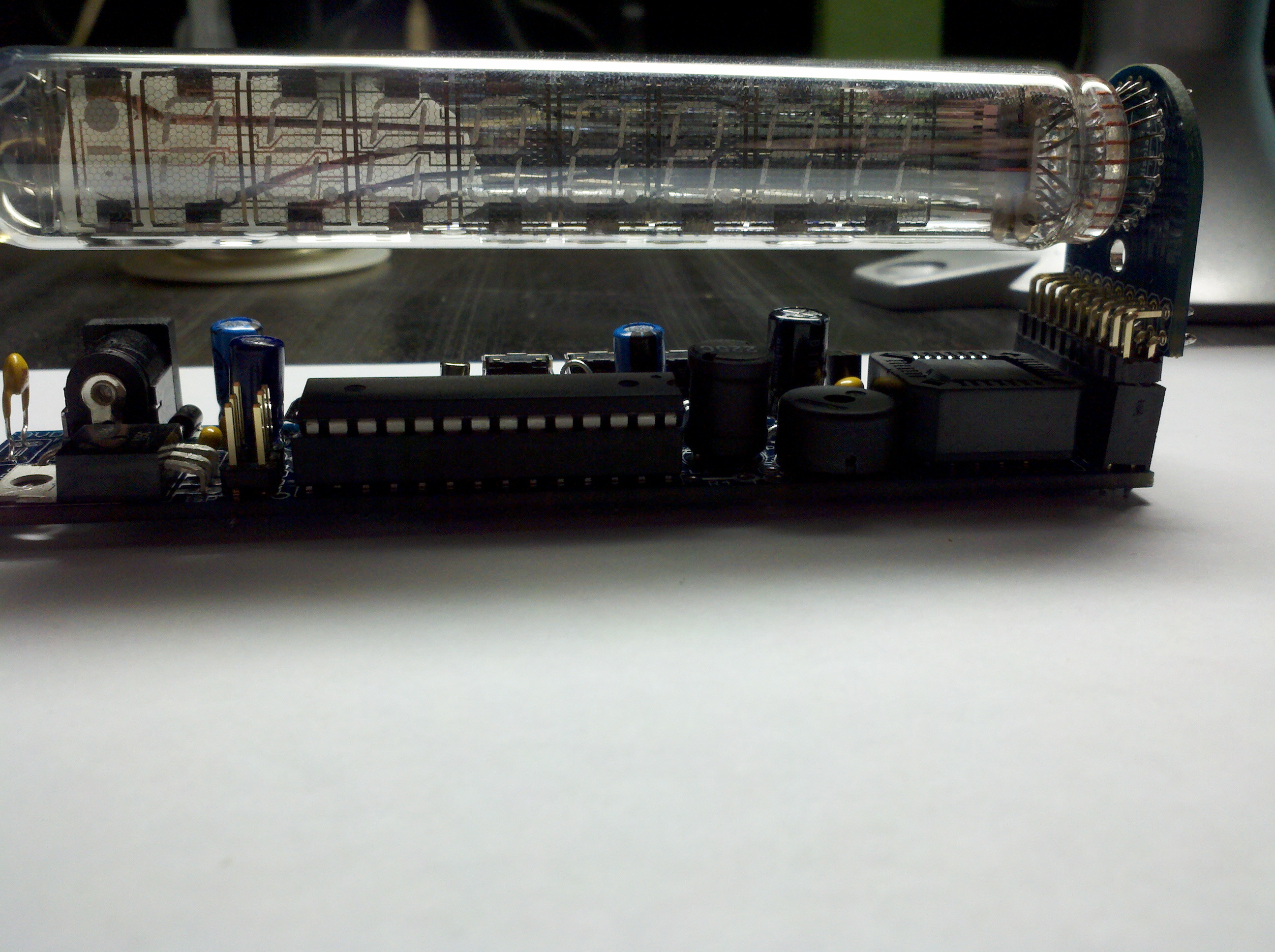 [/caption]
[caption id="attachment_383" align="alignnone" width="300" caption="The
assembled clock. Yay!"]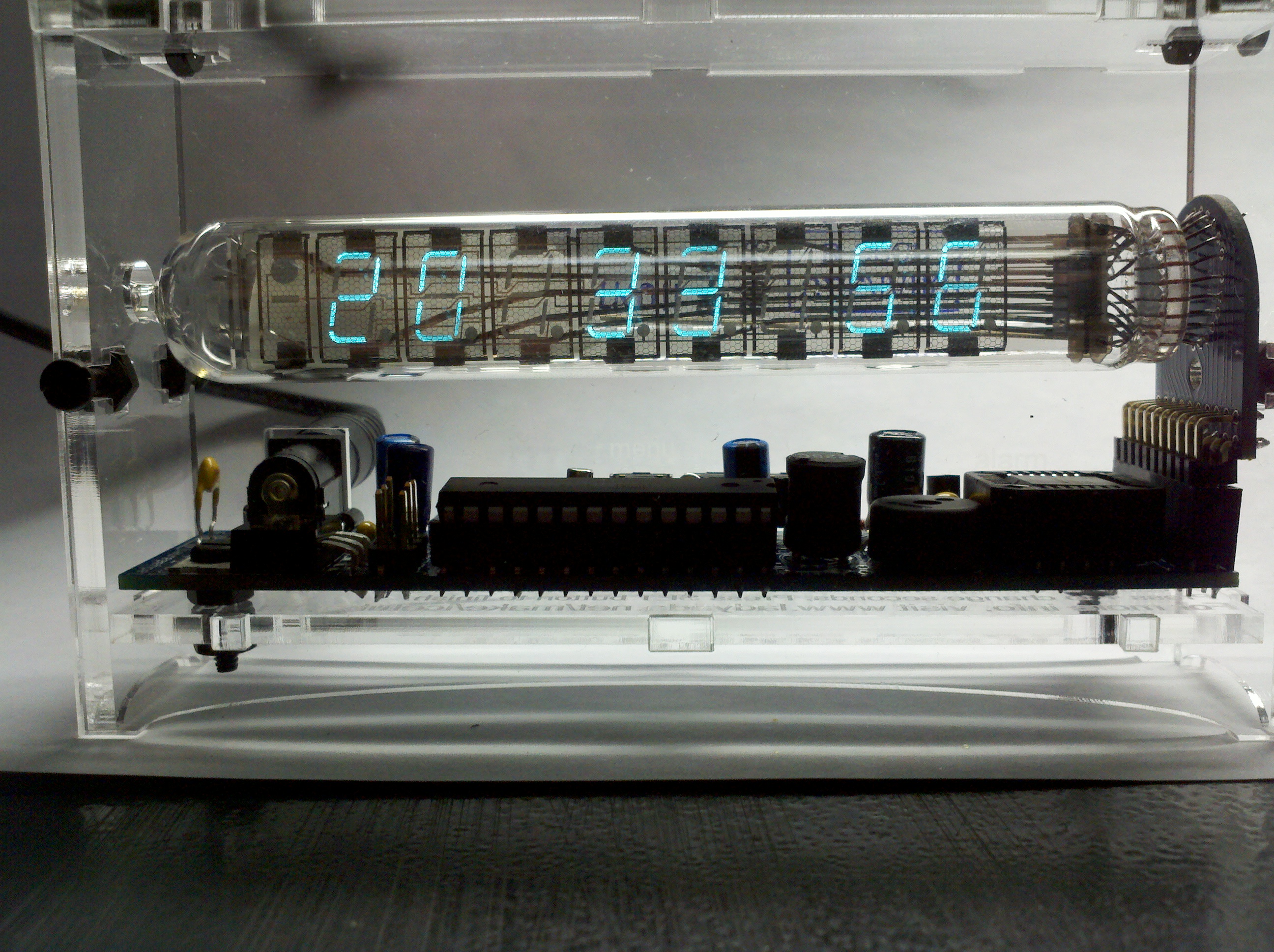 [/caption]